Every component you place on a PCB comes in one of two fundamental package styles: surface-mount (SMD) or through-hole (THT). Choosing the wrong type for your situation can mean boards that are hard to assemble, unnecessarily large, or expensive to manufacture. This article explains the tradeoffs so you can make an informed choice every time.
What Is Surface-Mount (SMD)?
Surface-mount components have flat metal pads or leads that sit directly on the PCB surface. They are soldered by applying solder paste to the pads, placing the component and running the board through a reflow oven (or carefully using hot-air rework). SMD is the dominant packaging technology in modern electronics manufacturing.
Common SMD package families you will encounter:
- Passives: 0402, 0603, 0805, 1206 (resistors, capacitors, inductors)
- ICs: SOIC, QFP, QFN, BGA
- Discretes: SOT-23, SOT-223 (transistors, regulators)
What Is Through-Hole (THT)?
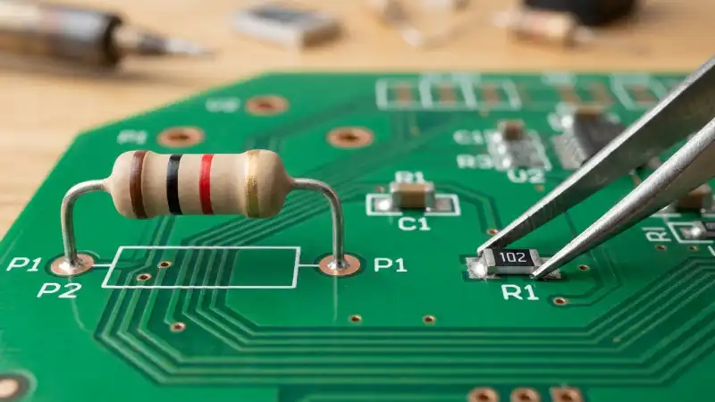
Through-hole components have long metal leads that pass through drilled holes in the board and are soldered on the opposite side. THT was the original PCB assembly method and is still widely used for connectors, large capacitors, DIP ICs and any component that needs mechanical strength.
SMD: Advantages and Disadvantages
Advantages
- Smaller footprint — an 0603 resistor is about 1.6×0.8 mm; the THT equivalent is ~10 mm long.
- No drilling required — SMD-only boards cost less to fab.
- Both sides of the board can be used for routing under SMD pads.
- Lower cost at production volume — pick-and-place machines handle SMD far faster than THT.
- Better high-frequency performance — shorter leads mean lower parasitic inductance.
Disadvantages
- Harder to hand-solder, especially packages below 0603 or fine-pitch ICs.
- Requires solder paste, a stencil and a heat source (oven or hot air).
- More difficult to replace/rework without proper tools.
Through-Hole: Advantages and Disadvantages
Advantages
- Easy to hand-solder with a basic iron — ideal for students and makers.
- Mechanically robust — leads pass through the board, making them strong against pull-out forces (great for connectors and large capacitors).
- Easy to desolder and replace using a solder sucker or wick.
- More beginner-friendly — pads are large and forgiving.
Disadvantages
- Larger physical footprint — limits board density.
- Requires drilled holes, which adds fab cost on some layers.
- Leads on the bottom prevent routing beneath the component on that layer.
When to Use Each
Use SMD when: board size matters, you are producing more than a handful of units, you need modern ICs (most new parts are SMD-only), or you are targeting a professional assembly workflow.
Use through-hole when: the component experiences mechanical stress (connectors, power jacks, large electrolytics), you are hand-assembling one or two prototypes, or you are working with DIP microcontrollers / sockets for easy swapping.
The Mixed Approach — Best of Both
Most professional boards use a hybrid strategy: SMD for passive components and ICs, through-hole for connectors, edge-mounted USB ports, screw terminals and any component subject to repeated plug/unplug cycles. This gives you compact board area while keeping the mechanically stressed parts reliable.
For your first student project: start with 0805 SMD passives (large enough to hand-solder with practice) and through-hole for all connectors. It is a forgiving combination that teaches both skills.
Ready to place your order?
5 boards — ₹450 total (₹150 setup + ₹300)
10 boards — ₹750 total (₹150 setup + ₹600) | Max 2 orders / month
Get a Quote →